IIAR BULLETIN #114 - 2019 REVISION
Ammonia markers have been developed to help contractors comply with ANSI / ASME A13.1-2015 standards for piping identification and IIAR's Recommended Guidelines, Bulletin #114 Identification of Ammonia Refrigeration Piping and System Components 2019 Revision.
Bulletin #114 2019 states that all piping mains, headers and branches should be identified as to the physical state of the refrigerant, i.e. vapor, liquid, etc., the relative pressure level of the refrigerant and the direction of flow. All components of the refrigeration system, e.g. receivers, heat exchangers, accumulators, etc., should also be uniformly identified.
Pipe markers in accordance with Bulletin 114, are designed to identify the refrigerant contained within that piping segment (i.e., ammonia) including the physical state of the refrigerant, relative pressure level of the refrigerant and direction of flow.
- Ammonia Piping Abbreviations: The 2019 revision contains 31 abbreviations versus 17 contained in the 1991 Guidelines. See full list below.
- Color changes: The background color for Ammonia pipe markers shall be Safety Orange, following the color guidelines by ANSI Z535.1 Safety Color Code.
- Color changes: The color for the LIQUID physical state has also changed, it used to be Orange and is now Yellow.
- Component/ Equipment Marker Abbreviations: in the 2019 revision IIAR has supplied a list of the most common component abbreviations. See full list below.
- Piping Color Scheme: the scope of this new section is to provide a suggested, non-mandatory color scheme beyond a simple 'one color' or 'two color' scheme for ammonia refrigeration piping systems in machinery rooms. The color schemes may also be applied to portions of the refrigeration system beyond machinery rooms. Existing schemes for identification are considered acceptable. In those areas where state codes and government regulations are not conflicted, ammonia refrigerated facilities have the option to implement a company documented piping color scheme.
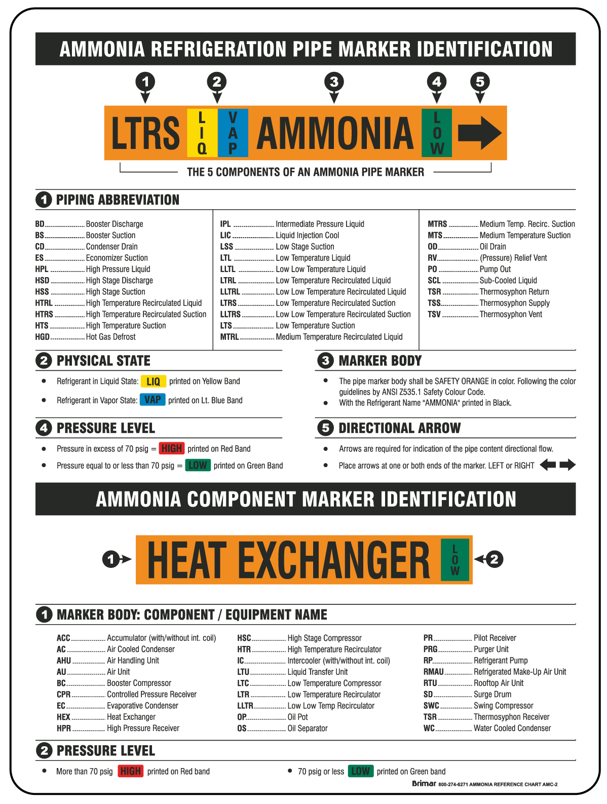
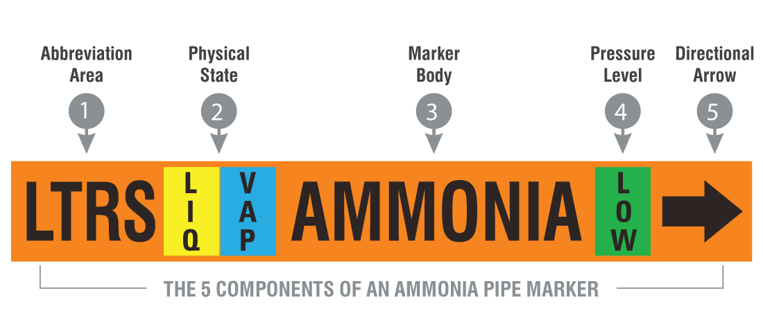
AMMONIA PIPE MARKER INFORMATION
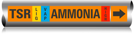
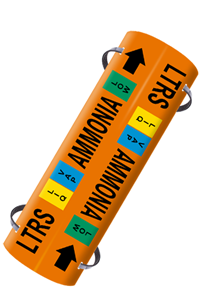
Ammonia pipe markers will contain or be divided in 5 section or components:
- Abbreviation Section: Printed in black
- Physical State Section: Either LIQUID or VAPOR
Printed in yellow for Liquid and sky blue for Vapor - Marker Body: Body color to be Safety Orange and contain the refrigerant "AMMONIA" printed in black
- Pressure Level Section: Either LOW or HIGH.
Pressure in excess of 70 psig will be considered to be high pressure and printed in black letters on a red band.
Pressure equal to or less than 70 psig will be considered to be low pressure and printed in black on a green band. - Directional Arrow: Detachable arrow printed in black.
PIPE MARKER SIZE CHART
The following chart shows the recommended pipe marker letter height and marker size based on the outside pipe diameter of the pipe to be identified and the distance between the viewer and the pipe.
Considering these factors, the size of the pipe marker and lettering should be selected to provide quick and positive identification. Pipe location, from a viewer's standpoint, will be different on every installation. Therefore, on-site decisions will be necessary to provide the optimum pipe marking system.
Brimar's Stick-On EZ Pipe Markers
-

Ammonia EZ Marker Style AN-1
For pipes with O.D. of 3/4" to 2"
Legend Size: 3/4" High
Marker Size: 1-1/2" h x 10" long
Marker comes with detachable directional arrow -
Ammonia EZ Marker Style AN-2
For pipes with O.D. of 2-1/2" to 6"
Legend Size: 1-1/4" High
Marker Size: 2-1/2" h x 15" long
Marker comes with detachable directional arrow
-
Ammonia EZ Marker Style AN-3
For pipes with O.D. of 7" to 10"
Legend Size: 2-1/2" High
Marker Size: 3-1/2" h x 27" long
Marker comes with detachable directional arrow -
Ammonia EZ Marker Style AN-4
For pipes with O.D. Over 10"
Legend Size: 3-1/2" High
Marker Size: 4-1/2"h x 32" long
Marker comes with detachable directional arrow
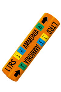
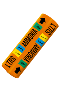
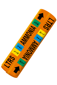
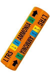
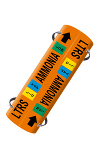
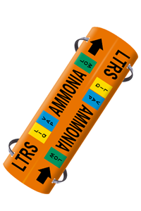
Brimar's Wrap Around & Strap-On System #1 Pipe Markers
-
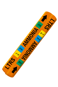
Ammonia System #1 Wrap Around Size RA
For pipes with O.D. of 3/4" to 1"
Legend Size: 1/2"
Marker Size: 8" -
Ammonia System #1 Wrap Around Size RB
For pipes with O.D. of 1-1/8" to 2-3/8"
Legend Size: 3/4"
Marker Size: 8"
-
Ammonia System #1 Wrap Around Size RC
For pipes with O.D.2-1/2" of to 3-1/4"
Legend Size: 1-1/4"
Marker Size: 12" -
Ammonia System #1 Wrap Around Size RD
For pipes with O.D. of 3-3/8" to 4-1/2"
Legend Size: 1-1/4"
Marker Size: 12"
-
Ammonia System #1 Wrap Around Size RE
For pipes with O.D. of 4-5/8" to 6"
Legend Size: 1-1/4"
Marker Size: 12" -
Ammonia System #1 Wrap Around Size RF
For pipes with O.D. of 6-1/8" to 7-7/8"
Legend Size: 1-1/4"
Marker Size: 12"
-
Ammonia System #1 Wrap Around Size RG
For pipes with O.D. of 8" to 10"
Legend Size: 2-1/2"
Marker Size: 24" -
Ammonia System #1 Wrap Around Size RH
For pipes with O.D. over 10"
Legend Size: 3-1/2"
Marker Size: 32"
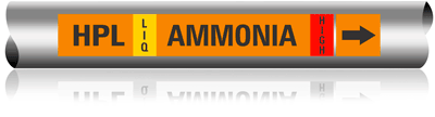
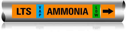
AMMONIA PIPE ABBREVIATIONS:
Abbreviating the names given to pipes in the ammonia refrigeration system will assist the operator in identifying and tracing the system. To further assist the operator make sure the physical state (LIQUID or VAPOR) as well as the pressure level (HIGH or LOW) are also identified in the marker. i.e., Adding -10° to a particular recirculated suction line and 0° to another one, would serve to differentiate between 2 Low Temp Recirculated Suction (LTRS) lines.
DIRECTIONAL ARROWS
Directional arrows will be printed on the marker body. In the case of the wrap around pipe markers, arrows & legends are printed repeatedly in opposite directions allowing the marker to be applied in any direction achieving proper reading while indicating pipe content flow. The "self-adhesive" type of marker will be printed with one directional detachable arrows. In either case, the directional arrow or arrowhead will be BLACK in color and proportionate in size to the marker. Directional arrow tape may also be applied around the full circumference of the pipe.
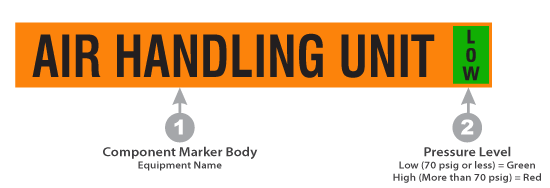
AMMONIA COMPONENT / EQUIPMENT MARKERS
1. Component markers will bear the name of the equipment they identify, e.g., RECEIVER, ACCUMULATOR, RECIRCULATOR, etc.
2. In addition, component markers will be provided with a pressure level designation.
Component markers will have BLACK letters on a SAFETY ORANGE field.
Pressure Level will be indicated by the word HIGH in RED letters or the word LOW in GREEN letters printed or applied flush with the right edge of the marker.
Brimar's component markers measure 24" x 3-1/2" and contain 2-1/2" high text.
COMPONENT MARKER ABBREVIATIONS:
Applying abbreviations of the names commonly given to components or equipment in an ammonia refrigeration system will assist the operator in identifying components and tracing system piping. In addition to the abbreviation, the use of a temperature or a pressure commonly associated with a particular line may further assist the operator.
AMMONIA REFERENCE CHART
A reference chart that fully explains the ammonia refrigeration piping and component identification markers, including the approved abbreviations, should be placed in areas that are conspicuous to operating personnel. Regardless of the piping color scheme selected, a legend or key to the meaning of the colors should be posted in a conspicuous area. The reference chart, legend, or key should be made of durable material that will remain legible.